At DEFCON in RF Village, we had a place to demonstrate work from ORI. We showed off open source synthetic aperture radar with coffee cans and GNU Radio and a PLUTO, and had space to show our “FT8 performance for keyboard chat” RFBitBanger QRP HF kit. We had room for the regulatory work for ITAR/EAR/219 MHz. And, very importantly – we had enough space to show major components of our UHF and up comms Opulent Voice system for amateur terrestrial and satellite fully up and running. At DEFCON, we had the human-radio interface and the modem as separate fully functional demonstrations.
Today, these two components have been combined and are working end-to-end. It’s coughing and sputtering, but it’s a solid first light. This means that microphone/keyboard/data processing from user input to waveforms over the air are happening.
The design goals for Opulent Voice project are to deliver very good voice quality in a modern way. AMBE/CODEC2 honestly sound terrible. Amateur radio deserves better audio quality. Therefore, we baseline Opus 16 kbps. It sounds great. Want more? there’s a path to 32 kbps.
We were very tired of a separate broken packet mode for data in ham digital voice product after ham digital voice product. Opulent Voice has keyboard chat and data in a single prioritized stream. No separate clunky packet mode. No 1980s architecture. It just works. In your browser. Or, at a command line interface. Chat only with transcriptions of all the audio received? With a microphone all in your ears and you never have to look at a screen? Your choice.
There are transcriptions for received audio (if you want that – it’s configurable), and text to speech for text messages is literally the next issue to be addressed. Accessibility is designed in from the start.
For terrestrial use, we have a demonstration conference server running on ORI’s Linode instance. This was up and running for DEFCON. It’s internet-only implementation of the repeater for terrestrial or space use, so that folks can see what the UI/UX looks like.
Everything is open source. Upcoming events? Opulent Voice will be presented to the ESA, AMSAT-DL, JAMSAT, and others in the next few months.
To everyone here that’s been supportive and wonderful – thank you so much.
RF Village has been instrumental and irreplaceable for this work to get a wider audience. This has been of enormous help. The benefits last year-round.
We’ve exhibited, presented, and contributed towards Ham Radio Village as well.
Here’s where we’ve been publishing and documenting the work. Under active decelopment. Approach with the usual caution.
Open Research Institute is a non-profit dedicated to open source digital radio work on the amateur bands. We do both technical and regulatory work. Our designs are intended for both space and terrestrial deployment. We’re all volunteer and we work to use and protect the amateur radio bands.
We equally value ethical behavior and over-the-air demonstrations of innovative and relevant open source solutions. We offer remotely accessible lab benches for microwave band radio hardware and software development. We host meetups and events at least once a week. Members come from around the world.
An ORI Recommended Off-the-Shelf Photogrammetry Method for Dish Surface Mapping at Deep Space Exploration Society
Opulent Voice Protocol Progress
Efficiently Using Transmitted Symbol Energy via Delay Doppler Channels
Inner Circle Sphere of Activity
What’s Double Doppler Shift in Radar? Or, Why Do We Have a Factor of Two?
11 May 2025
As part of our ongoing work to provide an Earth-Venus-Earth (EVE) communications link budget for amateur radio and citizen science use, we have updated several sections of the Jupyter Lab notebook.
Doppler spread happens when our signal reflects off a rotating structure, like Venus. Part of Venus (the East limb, on the right side of Venus as viewed from Earth) is moving towards us. And, part of Venus is moving away from us (the West limb, on the left side of Venus as viewed from Earth). The parts moving towards us cause reflected frequencies to increase. In the radar community, when a target is moving towards you, it produces a negative Doppler shift. The parts moving away from us cause reflected frequencies to decrease. In the radar community, when a target is moving away you, it produces a positive Doppler shift. The signal reflected off the center of the planet is reflected back with little to no frequency change. Doppler spread is a quantification of how muddled up our reflected signal becomes due to the rotation of the reflector.
Gary K6MG writes “A rough calculation of venus limb-to-limb doppler spreading @ 1296MHz: 4 * venus rotation velocity 1.8 m/s / 3e8 m/s * 1.296e9 c/s = 31 c/s. This calculation is the same as K1JT uses for EME in Frequency-Dependent Characteristics of the EME Path and is motivated from first principles. One edge of venus is approaching the earth at a 1.8m/s velocity relative to the center of venus, the other edge is receding at the same velocity giving one factor of 2. The other factor of 2 is due to the reflection, the wave is shortened or lengthened on both the approach and the retreat.”
You may be curious as to how the wave can be shortened or lengthened on both the approach and the retreat.
The double Doppler shift happens because radar involves a two-way journey of the radio wave. For example, a station on Earth may transmit a radio wave at exactly 1296 MHz. This wave travels toward Venus. When the wave hits a moving point on Venus’s surface (like the East or West limb), the wave’s frequency as experienced by that point is different from what was transmitted.
If the point is moving away from Earth, it “sees” a lower frequency (in other words, a redshift). If the point is moving toward Earth, it “sees” a higher frequency (in other words, a blueshift). The wave bounces off part of Venus’s surface. The wave is now re-emitted at the shifted frequency that the moving point “sees” or experiences. So the reflected wave already has one Doppler shift applied. As this already-shifted wave travels back to Earth, a second Doppler shift occurs. This is because the reflecting point is still moving, so the wave gets compressed or stretched again. The wave returns to Earth with two Doppler shifts applied. Therefore, there is a factor of two in the equation explained by Gary K6MG.
An example with real-world objects can help visualize what’s going on. Imagine throwing a tennis ball at a person on a moving train, and the train is coming right at you. You throw the ball to the person on the train at 10 mph. To the person on the train, your 10 mph ball appears to be moving faster or slower depending on the train’s direction. Since they are moving towards you, your 10 mph ball’s speed is added to the train’s 30 mph speed, and the ball would arrive at what felt like 40 mph. From their perspective, they received a 40 mph ball. Now they are just going to “reflect” the ball back at you at the same relative force as they received it. Now the ball is coming back to you at that 40 mph plus the velocity of the train, which is 30 mph. So you are going to be catching a 70 mph fast ball! When you receive the ball, its speed has been affected twice by the train’s motion.
This works in the other direction as well. Now that the train is moving away from you, it’s a lot harder to catch up to. So, you get a baseball pro, your friend Shohei Ohtani, to throw the ball for you. The train is moving away from you at 30 mph. Ohtani throws the ball at 100 mph. The person on the train catches it. It arrives at what feels like 70 mph to the person on the train. He tosses it back to Ohtani at 70 mph, because that’s how fast it arrived, relative to him. The train takes another 30 mph off the velocity of the ball, and Ohtani catches a ball going 40 mph.
The important insight about radar returns off of moving objects is that the reflection does not simply “bounce back” the original frequency. The moving reflector actually re-emits the signal at the Doppler-shifted frequency it receives, and then this already-shifted frequency undergoes a second Doppler shift on its return journey.
Fun Doppler Shift Challenge
While driving your car, you are stopped for running a red light. You tell the police officer that because of the Doppler shift, the red light (650 nm) was blueshifted to a green light (470 nm) as you drove towards the stop light. How fast would you have to be going in order for this to be true?
A) 0.5 times the speed of light
B) 0.3 times the speed of light
C) 0.1 times the speed of light
D) 0.01 times the speed of light
E) 70 mph
Namulus Crossword Puzzle
ACROSS
no longer a planet
long for the modulation scheme used in Opulent Voice
name of the human-radio interface project for Opulent Voice
short for the modulation scheme used in Opulent Voice
Want to represent ORI at this event? Join our Slack workspace and participate in the process of applying to present a talk, workshop, or roundtable. See https://openresearch.institute/getting-started
Information from Libre Space Foundation about the workshop is below:
Reignite the Open Source CubeSat Workshop!
Join Libre Space Foundation again for a two-day workshop to see how the open source approach can be applied to CubeSat missions with a focus on innovative and state-of-the-art concepts!
Open source software and hardware is empowering and democratizing all areas of life, so why not apply it to space exploration? The Open Source Cubesat Workshop was created exactly for that: to promote the open source philosophy for CubeSat missions and beyond. The sixth edition of the workshop takes place in Athens, Greece, hosted by Libre Space Foundation.
CubeSats have proven to be an ideal tool for exploring new ways of doing space missions; therefore, let’s remove the barrier of confidentiality and secrecy, and start to freely share knowledge and information about how to build and operate CubeSats. This workshop provides a forum for CubeSat developers and CubeSat mission operators to meet and join forces on open source projects to benefit from transparency, inclusivity, adaptability, collaboration and community.
The focus of this year’s workshop is to develop and apply open source technologies for all aspects of a space mission. The target audience of this workshop is academia, research institutes, companies, and individuals.
Starts Oct 25, 2025, 10:00 AM
Ends Oct 26, 2025, 6:00 PM
Europe/Athens – Serafio of the Municipality of Athens 19 Echelidon Street & 144 Piraeus Street 11854, Athens Greece
The workshop is free of charge but limited to 200 people.
“Take This Job”
30 May 2025
Interested in Open Source software and hardware? Not sure how to get started? Here’s some places to begin at Open Research Institute. If you would like to take on one of these tasks, please write hello@openresearch.institute and let us know which one. We will onboard you onto the team and get you started.
Opulent Voice:
Add a carrier sync lock detector in VHDL. After the receiver has successfully synchronized to the carrier, a signal needs to be presented to the application layer that indicates success. Work output is tested VHDL code.
Bit Error Rate (BER) waterfall curves for Additive White Gaussian Noise (AWGN) channel.
Bit Error Rate (BER) waterfall curves for Doppler shift.
Bit Error Rate (BER) waterfall curves for other channels and impairments.
Review Proportional-Integral Gain design document and provide feedback for improvement.
Generate and write a pull request to include a Numerically Controlled Oscillator (NCO) design document for the repository located at https://github.com/OpenResearchInstitute/nco.
Evaluate loop stability with unscrambled data sequences of zeros or ones.
Determine and implement Eb/N0/SNR/EVM measurement. Work product is tested VHDL code.
Review implementation of Tx I/Q outputs to support mirror image cancellation at RF.
Haifuraiya:
HTML5 radio interface requirements, specifications, and prototype. This is the primary user interface for the satellite downlink, which is DVB-S2/X and contains all of the uplink Opulent Voice channel data. Using HTML5 allows any device with a browser and enough processor to provide a useful user interface. What should that interface look like? What functions should be prioritized and provided? A paper and/or slide presentation would be the work product of this project.
Default digital downlink requirements and specifications. This specifies what is transmitted on the downlink when no user data is present. Think of this as a modern test pattern, to help operators set up their stations quickly and efficiently. The data might rotate through all the modulation and coding, transmitting a short loop of known data. This would allow a receiver to calibrate their receiver performance against the modulation and coding signal to noise ratio (SNR) slope. A paper and/or slide presentation would be the work product of this project.
An ORI Recommended Off-the-Shelf Photogrammetry Method for Dish Surface Mapping at DSES
Equipment Needed
DSLR or Mirrorless Camera: Any modern camera with 20+ megapixels (Canon, Nikon, Sony, etc.) Higher resolution is better, but even a good smartphone camera can work in a pinch. Fixed focal length (prime) lenses are preferred for consistency.
Tripod: For stable, consistent images. Or, a drone.
Reference Markers: Printed QR codes or ArUco markers. Reflective targets (can be made with reflective tape on cardboard). Tennis balls or ping pong balls (bright colors work well).
Measuring Tools: Laser distance meter for scale reference. Long tape measure. Spirit level
Software: Agisoft Metashape ($179 for Standard edition) OR free alternatives like Meshroom, COLMAP, or even WebODM
Process
Prepare the Dish: Place reference markers in a grid pattern across the dish surface. For an 18m dish, aim for markers every 1-2 meters. Include some markers at known distances for scale reference.
Capture Photos: Take photos from multiple positions around the dish, high and low. Ensure 60-80% overlap between adjacent images. Capture both wide shots and detail shots. For best results, take like 100+ photos of the entire structure. Take photos under consistent lighting (overcast days are best).
Process the Images: Import photos into photogrammetry software. Align photos to create a sparse point cloud. Generate a dense point cloud. Create a mesh and texture if desired. Will be very nice in presentations! Scale the model using your known reference distances.
Analysis: Export the point cloud as a CSV or PLY file. Use MATLAB, Python (with NumPy/SciPy), or specialized surface analysis software and use appropriate fitting functions to “fit” the point cloud to an ideal parabola. Calculate root mean square (RMS) error from the ideal surface. Generate contour maps of deviation. More great images for presentations!
Special Considerations for Radio Dishes
Dish Position: Ideally position the dish at zenith or a consistent angle for the full survey.
Reference Frame: Establish the feed support point and dish center as key reference points!
Example Workday Plan
Morning Session: Set up markers across the dish (2-3 hours)
Midday Session: Photograph dish from multiple angles (2-3 hours)
Afternoon/Evening: Process initial results on-site to verify quality (1-2 hours) don’t leave until the software workflow is confirmed!
Follow-up Analysis: Detailed surface error mapping and calculations (1-2 days or more)
This approach has been successfully used by amateur radio astronomy groups and small observatories to characterize dishes of similar size to DSES’s 18m antenna. The resulting data can directly inform the noise temperature calculations and help verify the antenna efficiency value (I believe 69%) we are currently using in our EVE link budget.
For DSES specifically, this could be implemented as a weekend workshop activity that would not only produce valuable technical data but also serve as an educational opportunity for members.
Do you see a way to improve this proposed process? Comment and critique welcome and encouraged.
Below: llustration-of-3D-spatial-reconstruction-based-on-SfM-algorithm.png from ResearchGate. This is an illustration of how a drone might assist with photogrammetry of a large dish surface.
Opulent Voice Protocol Development
Opulent Voice is an open source high bitrate digital voice (and data) protocol developed by ORI. It’s designed as the native digital uplink protocol for ORI’s broadband microwave digital satellite transponder project. Opulent Voice (OPV) can also be used terrestrially.
Locutus
The focus of most of the recent work has been on the minimum shift keying (MSK) modem, called Locutus. The target hardware for implementation is the PLUTO SDR from Analog Devices. See
https://github.com/OpenResearchInstitute/pluto_msk for source code, documentation, and installation instructions.
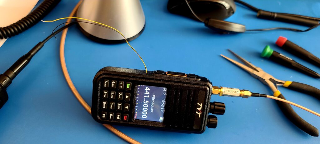
With the modem in an excellent “rough draft” state, with positive results in over-the-air testing, work on the human-radio interface has begun.
Introducing “Interlocutor”
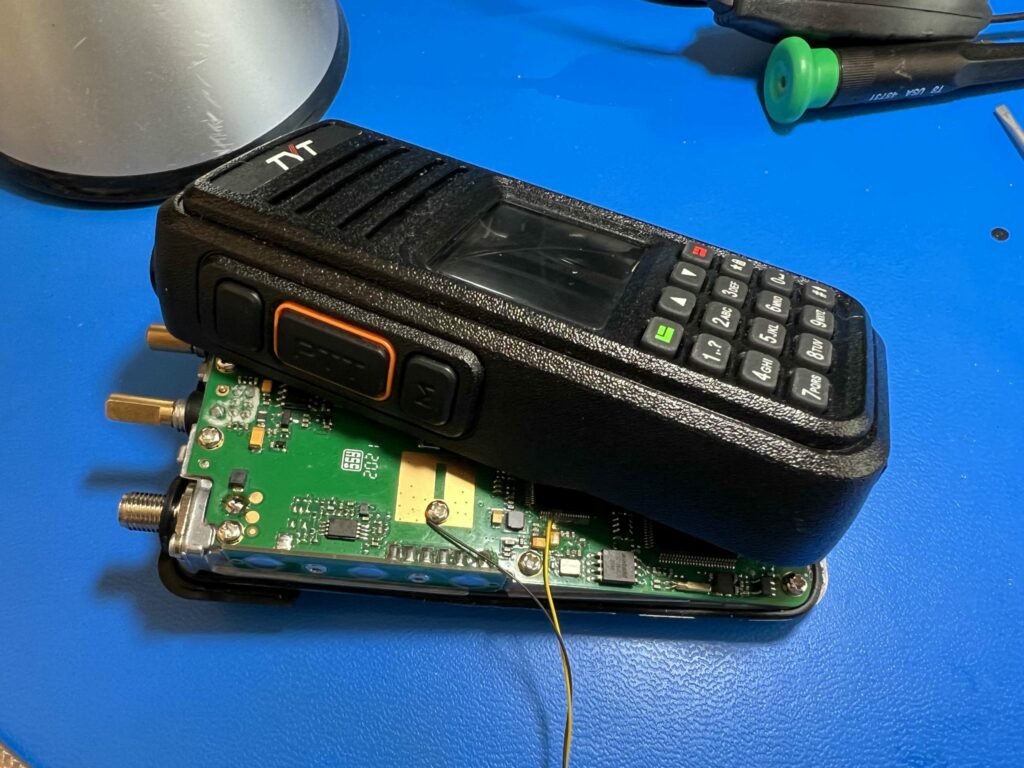
The human-radio interface is the part of the design that takes input audio, text, and keyboard chat and processes this data into frames for the modem. It also handles received audio, text, and data. The target hardware for this part of the design is a Raspberry Pi version 4, and the project name for this part of the radio system is called Interlocutor.
Why Not Just Use the PLUTO for Everything?
Why don’t we use the PLUTO SDR for handling the input audio, text, and data? For two reasons.
First, the field programmable gate array (FPGA) on the device, a Zynq 7010, can handle the modem design, but there isn’t a lot of space left over after it’s programmed to be an Opulent Voice transceiver. The ARM processor on the Zynq 7010 is a dual-core ARM Cortex-A9. This processor is fully up to the task of running many of the functions of an SDR, but experiments with encoding with Opus on the A9 caused some performance concerns.
Second, there are no dedicated microphone or headset jacks on the PLUTO SDR. Everything, a keyboard, monitor, and headphones, would need to be connected through USB. While this is a potential solution, we decided to try separating the two parts of this radio system at the natural dividing line. Namely, the stream of protocol frames that are ready to process into symbols. We do quite a lot of work to prepare the frames, as the voice, control, text, and data are multiplexed in priority order. Voice is encoded with Opus, and there are two different types of forward error correction. By doing all this work on a Raspberry Pi, the frames can then be sent out over Ethernet to the radio. This enables remote operation as well as providing a useful modularity in the design. As long as the modem knows what to do with the received frames, an Opulent Voice signal is created and sent out over the air. The same Raspberry Pi codebase can interface to any Opulent Voice modem, as long as it has Ethernet. This division of labor also easily enables Internet-only use.
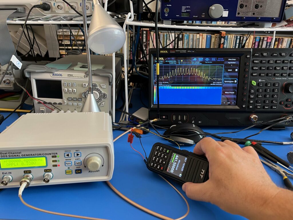
No Replacement for Demonstration
It doesn’t work until it works “over the air”, and Opulent Voice protocol development is no exception. Turning good ideas into actually physically working implementations is the real value of an open source effort. There are always things that are discovered when drawings and sequence diagrams become code and that code is run on real devices.
A Raspberry Pi was set up with Raspian OS. Python was chosen as the language to develop an Interlocutor. A momentary (push) switch was connected to general purpose input and output (GPIO) pin 23 and a light emitting diode (LED) was connected to GPIO pin 17.
The first order of business was to get GPIO input (push to talk button) and output (push to talk indicator light) working. After this, audio functionality was sorted out. A USB headset microphone was connected, the pyaudio library was used, and after some back-and-forth, receive and transmit audio was confirmed present.
Next was installing of opuslib, which handles the encoding of audio with the Opus voice encoder. This was the point where a Python environment was necessary to have, as library management became increasingly complex. Python environments are software “containers” for the all of the custom configurations needed to make interesting things happen in Python. Environments are the recommended way to handle things. After the environment was set up, the next challenge was to restrict Opus to constant bit rate of 16 kbs and to fix the frame length at 80 bytes. This was not as straightforward as one might hope, as direct access to the constant-vs-variable bit rate settings in opuslib did not appear to be available. Eventually, the correct method was found, voice data was sent to a desktop computer across the Remote Labs LAN, and a receiver script in Python played the audio sent from the Raspberry Pi. This was a great “lab call” milestone.
Getting the voice stream established allowed for iterative development. With each new function, voice transmission could be tested. If it stopped working, then it was highly likely that the most recent change had “broken” the radio.
Chat was added and iteratively improved until it was successfully integrated with voice. Voice has a higher priority than text. Text chat messages will not interrupt a voice call. They will be queued up and sent as soon as the push to talk button is released. One can also have just keyboard-to-keyboard chat over the air, similar to RTTY. Having the option to use voice or chat with the same radio and the same user interface is one of the goals of Interlocutor.
The protocol specification had control messages, for assembly, acquisition, access, authorization, and authentication, or A5 for short, as the highest priority traffic. These messages could therefore interrupt voice, text, or data communications.
A5 messages can be quite large. If these messages are very infrequent, then voice dropouts might be considered tolerable. However, we don’t really know how often a satellite will do authorization or authentication checks. That is up to the satellite or repeater operator. They may have a policy of anyone being able to use the resource at any time without any checking. Or, they may enforce any number of restrictive policies. There may be policies for emergency communications use, or a lot of A5 traffic for safety or shutdown reasons during mode changes. Since A5 traffic is the highest priority traffic, and since we really don’t know how often these messages will arrive, then we don’t know how much damage to voice calls will happen. Interlocutor development raised this issue. The solution currently being tested reverses the priority level of voice and A5 messages.
This means that an amateur operator could access the communications resource at most once with a voice call, before an A5 message could inform the station that it was not authorized or authenticated. This situation would occur if the satellite or repeater was permissive about access (which is something we do want, because we want people using their radios and talking to other hams) and let the amateur operator transmit first and “asked questions” later.
For example, an operator has been behaving badly on the air or harassing other operators. Their station ID may be added to a block list at the repeater. The repeater checks authentication and authorization, but only after people successfully access the resource. This would catch any blocked operators, but one voice transmission could potentially get through before the second-highest-priority A5 traffic was processed.
An obvious solution would be to do a full system authentication and authorization before any transmission is allowed at all. The downside to doing this is that it adds latency to accessing the satellite or repeater. We should try our very best to not have any worse performance in terms of ease of use when compared to a traditional FM repeater. Access latency is something that we are carefully tracking and monitoring during development, so any time the protocol can be modified to improve either the appearance or the actuality of latency, that is the choice we will make.
Accessibility
Using a Raspberry Pi (or similar computer) for Interlocutor also allows co-development for accessibility requirements. Opulent Voice must be as easy to use as possible. The Python script is currently a terminal program, but is designed to also be able to use an HTML5 interface. This is the second major modularity in the radio system.
The HTML5 interface is not in the code yet. Full functionality through a command line terminal access will be completed first, then the HTML5 interface written to expose all of the configuration and input and output from the terminal program. The goal is exactly the same behavior whether you are using Interlocutor from the command line or from a web browser.
Being able to run a radio using a browser means that the radio functions can be available on a very large number of devices, from ordinary computers using a keyboard or mouse, to screen readers, audio browsers, devices with limited bandwidth, old browsers and computers, and mobile phones and touch devices. It can be used by those with disabilities, senior citizens, and people with low literacy levels or temporary illness.
Our four areas of accessibility for Interlocutor are hearing, mobility, cognitive, and visual. HTML5 interface provides an enormous quantity of leverage in all four of these categories. While it may not be possible to design a perfectly accessible radio, we are committed to designing one as close to perfect as we can get. Accessibility improves the experience for everyone, so it’s more than worth doing.
Hearing
If you can’t hear, then how do you use our radio? First, Interlocutor has keyboard to keyboard or text chat mode built in. As long as you can see the screen and use a keyboard, you can use Opulent Voice. What about the voice traffic? There are several options. An operator may already have a trusted third party speech to text going on. However, since Opulent Voice uses Opus voice encoder, and since the voice quality is quite good, we can include speech-to-text in Interlocutor. There are cloud and local options for the Raspberry Pi, and we’re going to test Whisper https://github.com/openai/whisper as well as Faster-Whisper (fwhisper) https://github.com/SYSTRAN/faster-whisper
If the performance can’t be done with on-board solutions, then one of the cloud-based options will be considered. Speech-to-text would be one of the run-time options for Interlocutor.
All of the controls must be made easy to use without hearing. This means that the HTML5 layout will prioritize simplicity and accessibility and give clear cues about audio status. We will need specific advice here on how to lay out the page.
Mobility
If you have limited mobility, but you can use a browser, then you can operate Opulent Voice. The HTML5 interface will be simple and easy to use for people with limited movement. We understand that we need to support as wide a variety of inputs as possible and not get in the way of or prevent the use of any trusted third-party solutions that the radio operator already has up and running on their computer or device. We will not have keyboard traps in the interface, where you can “tab” in to a configuration setting, but then can’t “tab” back out. Want to take Interlocutor with you? The entire radio system, even as a prototype build, is not heavy or excessively bulky. The parts are all available off the shelf and can be set up all in the same location or in different locations, connected by Ethernet. Interlocutor can be with you wherever you are in your house, and the radio can be installed in a radio room. The push to talk button is on a GPIO pin in the current code base, it provides a hardware interrupt with minimal latency to the Interlocutor code, and it is very simple design to have a physical button on the radio case. However, this does mean you have to press down on the button as long as you want to talk. Someone with limited mobility may find this not easy or not even possible. A USB foot switch, to give just one example, is a very common way to activate a radio and may be a more accessible inclusion.
Cognitive
Configuration options will stay open as long as necessary for a radio operator to understand and select them. While Opulent Voice is an advanced and technical mode, it should not require the operator to be advanced or technical to fully enjoy it. There will not be any flashing lights or complicated graphics. The vocabulary for configuration will be consistent and simple. Since the code is open source, additional complexity, or an even simpler interface, can be exposed if desired with alternate HTML5.
Visual
Interlocutor must not get in the way or prevent the use of any third-party accessibility technologies that are used for visual impairments. It also must be as accessible as possible on its own. For visual accessibility, high-contrast displays, large buttons, and braille labels are commonly used. A Raspberry Pi in a case doesn’t have a lot of room for Braille labels, but incorporating them into a 3d printed case would be a good start. Some radios include voice prompts for navigation and settings, or integration with screen readers. There are radios that have incorporated braille keys. Part of the process of developing Interlocutor will be identifying what methods can be easily integrated into the code base.
What Happened Next?
What came next? The codebase had quite a bit of functionality. It delivered audio and chat frames, with priority Opulent Voice encoding, over Ethernet. Opus frames are the lowest layer of the protocol stack, and the Opulent Voice headers are the highest. Over the past few days, we installed RTP, UDP, and IP layers. This means that the stream of frames can now be handled by a very large number of existing applications.
With strenuous testing, a decision will be made whether this additional overhead is worth keeping or not. The only way we can make that decision with any confidence is to test the assumptions with real-world use. You can help.
Error correction still needs to be fully implemented, and a COBS encoder/decoder https://github.com/OpenResearchInstitute/cobs_decoder for distinguishing the frame boundaries of the non-Opus data. We are thinking that the division of labor will put this work on the modem side, keeping the Interlocutor focused on Internet data frames.
Want to Help?
If you would like to help make these and the many other things that we do happen more quickly or better, then you are welcome at ORI.
Please see the above article by Pete Wyckoff, KA3WCA. This is part one of a series about the technical side of modern Earth-Venus-Earth amateur radio communications. ORI is proud to present his work.
For more than 20 years, Peter S. Wyckoff has designed and tested a wide variety of digital communications systems, modems, and antenna arrays, particularly for the satellite communications industry. He graduated from Penn State University with an MSEE in 2000 and graduated from Pitt with a BSEE in 1997. Since graduation, he has been awarded seven U.S. patents, which are mostly about co-channel interference mitigation, antenna array signal processing, and digital communications.
ORI Inner Sphere of Activity
If you know of an event that would welcome ORI, please let your favorite board member know at our hello at openresearch dot institute email address.
28 May 2025 – ORI was represented by two volunteers at KiCon 2025, held at University of California at San Diego. The conference is the major North American event for KiCad, a free and open-source software suite for Electronic Design Automation (EDA).
13-23 June 2025 – Michelle Thompson is on the road in Arkansas, USA and will have some free time to meet up with volunteers and supporters.
20 Jul 2025 – Submission deadline for Open Source Cubesat Workshop, to be held 25–26 October 2025. Location is Serafio of the Municipality of Athens, Greece.
5 August 2025 – Final Technological Advisory Council meeting at the US Federal Communications Commission (FCC) in Washington, DC. The current charter concludes 5 September 2025.
7-10 August 2025 – DEFCON 33 in Las Vegas, Nevada, USA. ORI plans an Open Source Digital Radio exhibit in RF Village, which is hosted by Radio Frequency Hackers Sanctuary.
5 September 2025 – Charter for the current Technological Advisory Council of the US Federal Communications Commission concludes.
25-26 October 2025 – Open Source CubeSat Workshop, Athens, Greece.
Thank you to all who support our work! We certainly couldn’t do it without you.
Anshul Makkar, Director ORI Frank Brickle, Director ORI (SK) Keith Wheeler, Secretary ORI Steve Conklin, CFO ORI Michelle Thompson, CEO ORI Matthew Wishek, Director ORI
Open Research Institute is a non-profit dedicated to open source digital radio work. We do both technical and regulatory work. Our designs are intended for both space and terrestrial deployment. We’re all volunteer.
Membership is free. All work is published to the general public at no cost. Our work can be reviewed and designs downloaded at https://github.com/OpenResearchInstitute
We equally value ethical behavior and over-the-air demonstrations of innovative and relevant open source solutions. We offer remotely accessible lab benches for microwave band radio hardware and software development. We host meetups and events at least once a week. Members come from around the world.
Person 1: Hey, whatcha doing? Looks like something cool.
Person 2: Working on a Simulink model for an MSK model.
Person 1: Oh, that’s fun, how about I code up the modem in VHDL this weekend?
Person 2: Sounds great!
Famous last words, amirite? It has been many months – ahem 10 – since that pseudo conversation occurred. In that time there have been missteps, mistakes, and misery. We have come a long way, with internal digital and external analog loopback now working consistently, although unit to unit transmission isn’t quite there yet.
This is one way to do hardware development. Write some HDL code, simulate, and iterate. Once the simulation looks good, put it in an FPGA, test it, and iterate. You’ll get there eventually, but there will be some hair pulling and teeth gnashing along the way. But, it is worth the effort when you finally see it working, regardless (and because) of all the dumb mistakes made along the way.
There are many ways to approach a design problem, some better than others, and as with all things engineering, it’s a trade-off based on the overall design context. At opposing ends of the spectrum we have empirical and theoretical approaches. Empirical: build based on experience, try it, fix it, rinse and repeat. And, theoretical: build based on theory, try it, fix it, etc. Ultimately we must meet in the middle (and there is never getting away from the testing and iterating).
Starting from first principles always serves us well. One of the niggling points in the Minimum-Shift Keying (MSK) development has been selection of bit-widths for the signal processing chains.
Person 1 (yeah, that’s me): I’ll code it up this weekend. Let’s see, for the modulator we need data in, that’s 1-bit. The data gets encoded, still 1-bit. The data modulates a sine wave, hmmm, how many bits should that be? Well the DAC is 12-bits, so we should use a 2’s complement 12-bit number. That seems right.
Person 1: Now for the demodulator. The ADC outputs 12-bits, so a 2’s complement 12-bit number. That gets multiplied by a sine wave, let’s use a 2’s complement 12-bit number since we did that in the modulator. The multiply output is 24-bits, ok. Now we integrate that 24-bit number over a bit-period, hmmm, how many bits after the integration? No worries, let’s just make it 32-bits and keep on. But that is a lot of bits, let’s just scale the 32-bits down to 16-bits and keep going. Ah, the empirical approach, I’m getting so much done!
Person 1: Why isn’t this working? Oh, the 16-bit number is overflowing. I wish I could just make it 32-bits again, but that’s too many bits for the multiplier.
There is a better way! We can analyze the design from some starting point, such as, the number of input bits. From there we operate on those bits, adding, subtracting, multiplying, shifting, etc. And we know how each of those operations affects the bit widths, which allows us to choose appropriate bit-widths through the signal chain. Before we get there we need to take a quick look at fixed point math and related notation.
In our everyday base 10 math we have, essentially, infinite precision. One example is that irrational numbers can be expressed as fractions, and we can operate on those fractions and the infinite precision is maintained as long as we can keep the fractional representation. Often, though, we will need to use an approximation of the fraction to get an actual answer to a problem. One example is 1/3=0.33333… and we have to choose how many digits of 3 we need for the particular problem at hand. And, we know there is an error term when we use such an estimation (1/3=0.333+).
Base 2 math is largely the same, but hardware can’t use fractional representations, meaning that an irrational number will always be a finite representation. Also, we may be constrained in how many bits we can use to represent numbers. We need a way to notate these numbers.
Texas Instruments created Q-notation as a way to specify fixed-point numbers. The notation Qm.n is used to represent a signed 2’s complement number where m is the number of whole bits and n is the number of fractional bits. TI specifies m to not include the sign-bit, while ARM specifies m to include the sign bit. The table below shows examples of Q-notation using both TI and ARM variants.
Table 1. Q-Notation Examples
Total Bits
ARM Q Format
TI Q Format
Range
Resolution
8
Q3.5
Q2.5
-4.0 to +3.96875
2−5
16
Q4.12
Q3.12
-8.0 to +7.9997558594
2−12
24
Q8.16
Q7.16
-128.0 to +127.9999847412
2−16
32
Q8.24
Q7.24
-128.0 to +127.9999999404
2−24
8
UQ8.3
UQ8.3
0.0 to +255.875
2−3
10
Q1.10
Q10
-1.0 to +0.9990234375
2−10
The table below shows how bit widths are affected by various operations.
Table 2. Math operators affect on bit-widths
Operation
Input Numbers
Output
+/-
Qm.n +/- Qx.y
Qj.k where j = max(m,x)+1 and k = max(n,y)
*
Qm.n * Qx.y
Q(m+x).(n+y)
>>
Qm.n >> k
Qm.(n-k)
<<
Qm.n << j
Qm(n+j)
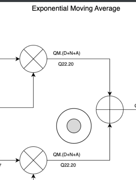
The diagram below shows an exponential moving average circuit with signal bit-widths notated as Qm.d. You can see the bit widths adjusted as we shift, multiply, add, etc. Since the output is an average of the input, it should have the same representation as the input (Qm.d). The lower representation (i.e. Q22.0 for the input) is an actual bit-width selection based on targeting the Zynq7010 and its 25×18 hardware multipliers. Some particular notes:
The Q22.0 input is specified by the surrounding system. It is left-shifted by 2-bits (Q22.2) to fully utilize the 25-bit multiplier input thus increasing the resolution.
The alpha input is specifically chosen to be Q17 to fully utilize the 18-bit multiplier input.
The bottom multiplier is in a feedback path, its output must match the upper multiplier output so that the binary points are aligned into the adder. To this end the adder output is truncated and rounded by 18-bits.
Figure 1. Exponential Moving Average Block Diagram
The adder output is truncated and rounded by 20-bits for the final output.
In summary Q-notation is a useful tool for understanding and specifying system bit-widths throughout the processing chain. It is especially useful to add Q-notation to the block diagram to help visualize the bit-widths. With this approach the optimal bit-widths should become apparent when taking into account system requirements. Doing this system analysis step before writing any code will save time and effort by reducing errors. The other benefit is that device resources are not over utilized, which may make the difference between fitting in an FPGA or not.
Additional reading and resources are available at these URLs:
A Python package for Fixed-point math is at fixedpoint 1.0.1 Package Documentation including explanations of Q-notation and how bit-widths are affected by arithmetic.
As the saying goes, mind your Ps and Qs.
Matthew Wishek, NB0X
Opulent Voice moves from real to complex modulation. Read on to find out more!
Real and Complex Signal Basics
The magic of radio is rooted in mathematics. Some of that math can be complicated or scary looking. We are going to break things down bit by bit, so that we can better understand what it means when we say that we are going to transmit a complex baseband signal.
Everything that we are going to talk about today is based on a single carrier real signal, even when we get to complex transmission. A single carrier real signal is where we take our data, a single-dimensional value that we want to communicate, and we multiply it by a carrier wave (a cosine wave) at a carrier frequency (fc). Let’s call the value we want to communciate “alpha”.
Because we are dealing with digital signals, the value that we are transmitting is held for a period of time, called T. The next period of time we send another constant value. And, so on. We are sending discrete values for a period of time T, one after another until we are all done sending data, and not continuous values over time.
Let’s say we are sending four different amplitudes to represent four different values. During each time period T we select one of these four amplitude values. We hold that value for the entire time period. These values can be thought of as single dimensional values. One value uniquely identifies the value we want to send. In this case, amplitude.
Sending one of four values at a time means we are sending two bits of data at a time.
alpha
bits
0
00
1
01
2
10
3
11
In order to send our value out over the air from transmitter to receiver, we multiply our alpha by our carrier frequency. The result is alpha*cos(2*pi*fc*t). Cosine is a function of time t. The 2*pi term converts radians per second to cycles per second, which is something that most of us find easier to deal with. When we multiply in the time domain, we cause a different mathematical thing to happen in the frequency domain. Multiplication is called convolution in the frequency domain. This mathematical process creates images, or copies, of our baseband signal in the frequency domain. One image will be located at fc and the other will be located at -fc.
Our real signal has a special characteristic. It’s symmetric. At the receiver, we multiply what we receive by that same cosine wave, cos(2*pi*fc*t). We multiply in the time domain, and we convolve in the frequency domain. This results in images at 2*fc, -2*fc, and most useful to us, we get two images at 0 Hz. We use a low-pass filter to get rid of the unwanted images at 2*fc and -2*fc, and by integrating over the time period T, we get a scaled version of the original value (alpha) that was sent. Amazing! We reversed the process and we got our original sent value.
So what’s all this complex signal stuff all about? Why mess with success? We have our single carrier signal and our four values. What more could we want?
Well, we want to be able to send more than a shave and a haircut number of bits!
If we want to send more bits in the same time period (and who doesn’t?) then we must use a bigger alphabet. Let’s double our throughput. We now pick from sixteen different amplitudes, sending the value we picked out for a period of time T as a single-carrier real signal. Now, each alpha value stands for four bits.
We have a minor problem. Sending out sixteen different voltage levels on a single carrier means that we have to be able to differentiate between finer and finer resolution at our receiver. Before, we only had to distinguish between four different levels. Now we have sixteen. This means we better have a really clear channel and a lot of transmit power. But, we don’t always have that. It’s expensive and a bit unreasonable. There is a better way.
We know we now want to send out (at least) one of sixteen values, not just one of four. If we turn our one-dimensional problem into a two-dimensional problem, and assign a real single carrier signal to, say, the vertical dimension, and then a second real single carrier signal to the horizontal dimension, then we are now enjoying the outer limits of digital signal processing. The vertical handles four levels. The horizontal handles four levels.
We still have the same time period T. We just have a two-dimensional coordinate system instead of a one-dimensional coordinate system.
alpha
bits
alpha
bits
0
0000
8
1000
1
0001
9
1001
2
0010
10
1010
3
0011
11
1011
4
0100
12
1100
5
0101
13
1101
6
0110
14
1110
7
0111
15
1111
But how can we send two real signals over the air, at the same time? We can’t just add them together, can we? They will step on each other and we’ll get a noisy mess at the receiver. Math saves us! We can actually add these two signals together, send them as a sum, and then extract each dimension back out. But, only if we prepare them properly. And here is how that is done.
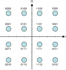
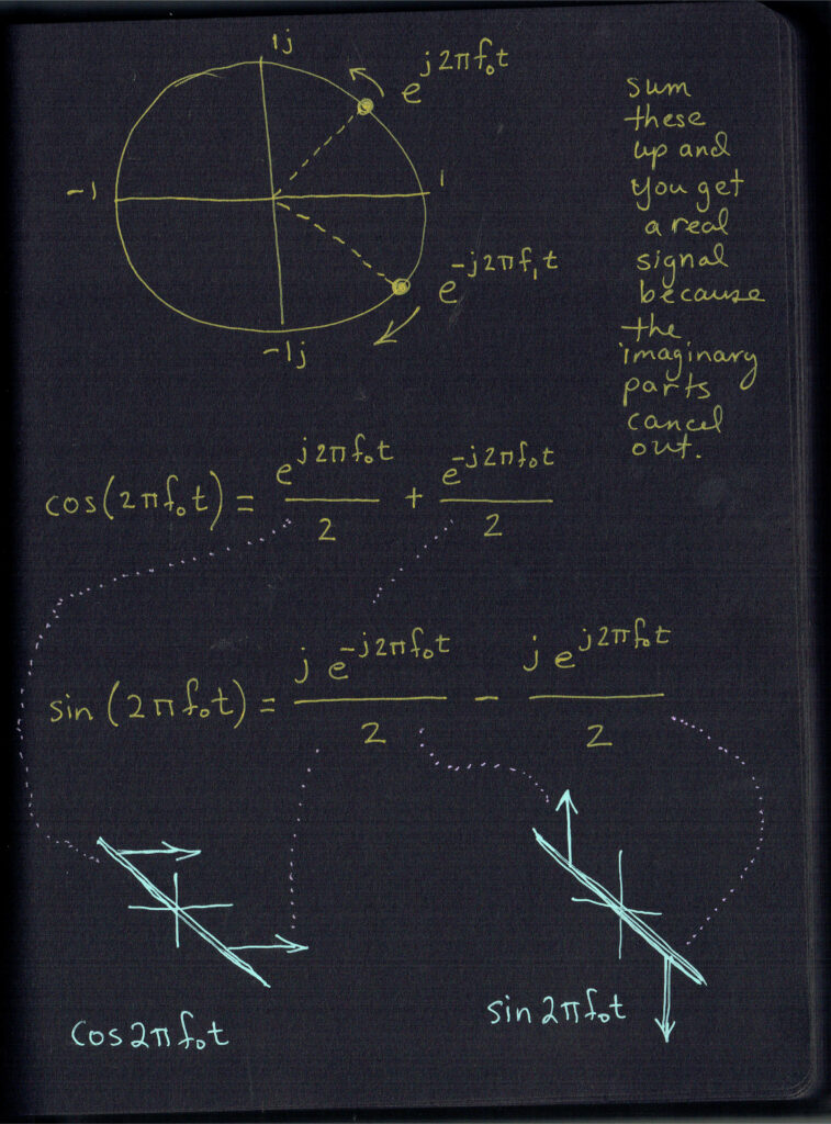
Look at the two-dimensional diagram of 16QAM. The vertical axis is labeled Q, and the horizontal axis is labeled I. When we want to indicate the vertical dimension of our value (pick any one of them), then we take that vertical dimension (say, -1 for 1111) and we multiply it by sin(2*pi*fc*t). We now have our Q signal. Now we need the horizontal location of 1111. That would be +1 on the I axis. We multiply this value, giving the horizontal dimension, by cos(2*pi*fc*t). We now have our I signal. Q axis value was multiplied by sine. I axis value was multiplied by cosine. These signals are played for the duration of the sample period. Both of them happen at the same time to give a coordinate pair for a particular alpha.
We add the I and Q signals together and transmit them. We are sending (I axis value) * cos(2*pi*fc*t) + (Q axis value) * sin(2*pi*fc*t).
At the receiver, we take what we get and we split the signal. We now have two copies of what we received. We multiply one copy by cos(2*pi*fc*t). We multiply the other by sin(2*pi*fc*t). We integrate over our time period T. This is important because it lets us take advantage of several trig identities.
First, let’s multiply and distribute our cos(2*pi*tfc*t) across the summed signals we received. We multiply:
Aha! We can convert that cos2() term to something we can use. Use the half angle identity, square each side, and double all the angle measurements (easy, right?). After this cleverness, this is what we have.
cos2(2*pi*fc*t) = 1/2*[1 + cos(2*pi*2fc*t)]
So now we have
(I axis value) * 1/2*[1 + cos(2*pi*2fc*t)]
See that 2fc term in there? Check out the notebook drawing for our signal in the frequency domain. It’s at 2fc. Q signal is on the right-hand half of the drawing.
Let’s rearrange things.
(I axis value/2) + [(I axis value/2) * cos(2*pi*2fc*t)]
Remember we are integrating over time at the receiver. We have one of the two terms rewritten in a useful way. What happens when we integrate a cosine signal from 0 to T? That value happens to be zero! This leaves just the integration of (I axis value/2)!
The result at the receiver for the multiplication and integration of the first copy of the received signal is (I axis value)*(T/2). We know T, we know what the number 2 is, so we know the I axis dimension value.
But wait! We forgot something. We only did the first part.
We recovered I axis value from the term before the plus sign. But what about the term after the plus sign?
(Q axis value) * sin(2*pi*fc*t)*cos(2*pi*fc*t)
Uh oh we didn’t get away from summing the I and Q together after all…
Trig saves us here too. When we integrate sin(2*pi*fc*t)*cos(2*pi*fc*t) from 0 to period T, it happens to be zero. The entire Q axis value term drops out. Does the same technique work for the copy of the received signal that we multiply by sin(2*pi*fc*t)?
You bet it does! First, let’s multiply and distribute our sin(2*pi*tfc*t) across the second copy of the summed I and Q signals we received. We multiply:
Now that we know that integrating cos(2*pi*fc*t)sin(2*pi*fc*t) from 0 to T is zero, we can drop out the I axis value term. That’s good because we already have it from multiplying our received summed signal by cos(2*pi*fc*t) and doing trigonomtry tricks.
We are left with
(Q axis value) * sin(2*pi*fc*t)*sin(2*pi*fc*t)
And we rewrite it
(Q axis value) * sin2(2*pi*fc*t)
And use the half angle trig identity, square each side, and then double all angle measurements.
Hey, guess who goes to zero again? That’s right, cosine integrated from 0 to T is zero. We are left with a constant term that integrates out to (Q axis value) * (T/2)
So when we multiply the summed signal that we received by cosine, we get I axis value. When we multiply the summed signal that we received by sine, we get Q axis value.
I and Q give us the coordinates on the 16 QAM chart. As long as we are in sync with our transmitter (a whole other story) and as long as our map of which point stands for which label (read your documentation!) is the same as at the transmitter, then we have successfully received what was sent using a technique called quadrature mixing.
Moving from a single carrier real signal to a “complex” signal, where two real signals are sent at the same time using math to separate them at the receiver, gives us advantages with respect to sending more bits without having to send more levels. Our two signals are each handling four levels, but using the results in a two-dimensional grid gives us more bits per unit time without having to change our performance expectations. Sending sixteen different levels is harder than sending four. So, we send four twice and use some mathematical cleverness.
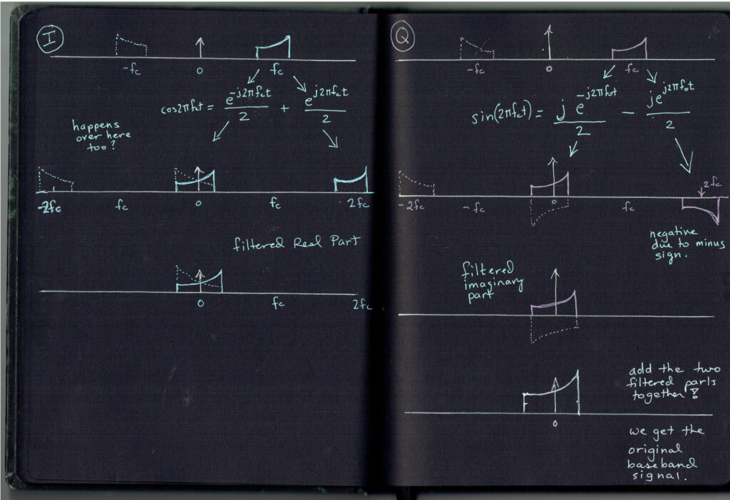
However, doing this complex modulation scheme gives us yet another advantage. Because of the math we just did, we eliminate an entire image when compared to a single carrier real signal. We have a less difficult time with filters because we no longer create a second image. Below (next page) are some diagrams of how this happens.
A third advantage of I and Q modulation is that it doesn’t just do things like 16QAM. Using an I and a Q, and a fast enough sample period T, means you can send any type of modulation or waveform. Now that’s some power!
This technique does require some signal processing at the receiver. But, this type of signal handling is at the heart of every software defined radio. And, now you know how it’s done, and the reasons why Opulent Voice is now using complex modulation in the PLUTO SDR implementation.
-Michelle Thompson W5NYV
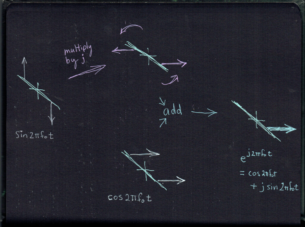
(Below are two more pages from our lab notebook, showing a few more visual representations. Don’t let the exponential functions worry you – “e” is a more compact way of representing the sine and cosine functions. In our notebook we show how sine and cosine can add to a single image. We can do this because sine and cosine are independent in a special way. This quality of “orthogonality” is used in all digital radios.)
Adding a Preamble to Opulent Voice
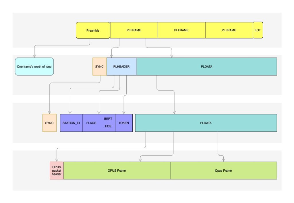
Looking at the Opulent Voice protocol overview diagram below, we can see that each transmission begins with a preamble. This section of the transmission contains no data, but is extremely helpful in receiving our digital signal.
The preamble is like a lighthouse for the receiver, revealing a shoreline through the fog and darkness of interference and noise. While we may not need the entire 40 milliseconds of preamble signal to acquire phase and frequency, so that we are “on board” for the rest of the transmission, keeping the preamble at the length of a frame simplifies the protocol.
There is a similar end of transmission (EOT) frame, so that the receiver knows for sure that the transmitted signal has ended, and has not simply been lost. This will reduce the uncertainty at the receiver, and allow it to return to searching for new signals faster and more efficiently.
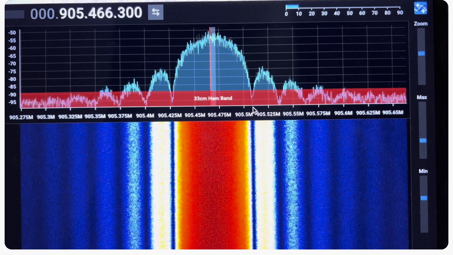
For minimum shift keying, the modulation of Opulent Voice, a recommended preamble data stream in binary is 1100 repeating. In other words, we’d get a frame’s worth of 11001100110011001100… at 54.2 kilobits per second for 40 milliseconds.
After the preamble is sent, data frames are sent. Note that there is a synchronization segment at the beginning of each frame. This keeps the receiver from drifting and improves reliability.
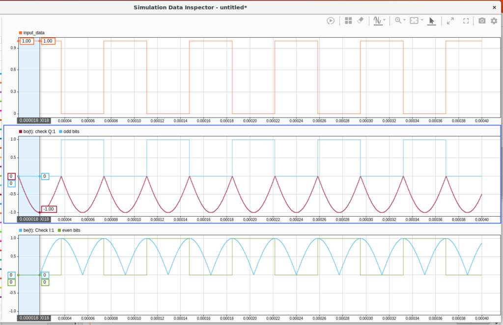
Constructing the Preamble in Simulink and in HDL
Below is the Simulink model output viewer showing the 1100 repeating pattern mathematical construction, followed by the planned update for the hardware description language (HDL) code updates. The target for HDL firmware is the PLUTO SDR. -Opulent Voice Team
“Take This Job”
Interested in Open Source software and hardware? Not sure how to get started? Here’s some places to begin at Open Research Institute. If you would like to take on one of these tasks, please write hello@openresearch.institute and let us know which one. We will onboard you onto the team and get you started.
Opulent Voice:
Add a carrier sync lock detector in VHDL. After the receiver has successfully synchronized to the carrier, a signal needs to be presented to the application layer that indicates success. Work output is tested VHDL code.
Bit Error Rate (BER) waterfall curves for Additive White Gaussian Noise (AWGN) channel.
Bit Error Rate (BER) waterfall curves for Doppler shift.
Bit Error Rate (BER) waterfall curves for other channels and impairments.
Review Proportional-Integral Gain design document and provide feedback for improvement.
Generate and write a pull request to include a Numerically Controlled Oscillator (NCO) design document for the repository located at https://github.com/OpenResearchInstitute/nco.
Generate and write a pull request to include a Pseudo Random Binary Sequence (PRBS) design document for the repository located at https://github.com/OpenResearchInstitute/prbs.
Generate and write a pull request to include a Minimum Shift Keying (MSK) Demodulator design document for the repository located at https://github.com/OpenResearchInstitute/msk_demodulator
Generate and write a pull request to include a Minimum Shift Keying (MSK) Modulator design document for the repository located at https://github.com/OpenResearchInstitute/msk_modulator
Evaluate loop stability with unscrambled data sequences of zeros or ones.
Determine and implement Eb/N0/SNR/EVM measurement. Work product is tested VHDL code.
Review implementation of Tx I/Q outputs to support mirror image cancellation at RF.
Haifuraiya:
HTML5 radio interface requirements, specifications, and prototype. This is the user interface for the satellite downlink, which is DVB-S2/X and contains all of the uplink Opulent Voice channel data. Using HTML5 allows any device with a browser and enough processor to provide a useful user interface. What should that interface look like? What functions should be prioritized and provided? A paper and/or slide presentation would be the work product of this project.
Default digital downlink requirements and specifications. This specifies what is transmitted on the downlink when no user data is present. Think of this as a modern test pattern, to help operators set up their stations quickly and efficiently. The data might rotate through all the modulation and coding, transmititng a short loop of known data. This would allow a receiver to calibrate their receiver performance against the modulation and coding signal to noise ratio (SNR) slope. A paper and/or slide presentation would be the work product of this project.
The Inner Circle Sphere of Activity
January 6, 2025 – All labs re-opened. Happy New Year!
January 13, 2025 – ORI presented to Deep Space Exploration Society about our history and projects line-up.
January 18, 2025 – San Diego Section of IEEE Annual Awards Banquet. ORI volunteers supported this event as a media and program sponsor. ORI was represented by five members.
January 23-26, 2025 – IEEE Annual Meeting for Region 6 and Region 4, ORI was represented by three members.
January 28, 2025 – Co-hosted the IEEE Talk “AI/ML Role in RTL Design Generation” with the Information Theory Society and the Open Source Digital Radio San Diego Section Local Group.
February 18, 2025 – San Diego County Engineering Council Annual Awards Banquet. ORI will be part of the IEEE Table display in the organizational fair held on site before dinner. ORI will be represented by at least one member.
Thank you to all who support our work! We certainly couldn’t do it without you.
Welcome to Open Research Institute’s Inner Circle Newsletter for December 2024. We have a lot to share with you!
Open Research Institute is a non-profit dedicated to open source digital radio work. We do both technical and regulatory work. Our designs are intended for both space and terrestrial deployment. We’re all volunteer. You can get involved by visiting https://openresearch.institute/getting-started
Membership is free. All work is published to the general public at no cost. Our work can be reviewed and designs downloaded at https://github.com/OpenResearchInstitute
We equally value ethical behavior and over-the-air demonstrations of innovative and relevant open source solutions. We offer remotely accessible lab benches for microwave band radio hardware and software development. We host meetups and events at least once a week. Members come from around the world.
Read on for regulatory, technical, and social articles. We close with a calendar of recent and upcoming events.
Want to subscribe to the Inner Circle? Sign up at http://eepurl.com/h_hYzL
Previous issues of Inner Circle can be found at https://www.openresearch.institute/newsletter-subscription/
Federal Communications Commission License DB (FCC LicDB) is a set of tools for exploring the FCC license database dumps. The tools are at https://github.com/tarxvftech/fcc_licdb
What you see in FCC LicDB is a way to download and then import most of the weekly database dumps to an sqlite database. Expect a couple gigabytes for uls.db, depending on how many services you import.
After that, the purpose of this repository gets more esoteric because it’s less about exploring and more about answering. (Answering what?)
There’s a problem with the 219-220 MHz amateur band. 47 CFR part 80 defines this band (among others) as for Automated Maritime Telecommunications Systems (AMTS), but that idea completely failed and so now there are no AMTS stations, just companies licensed for AMTS, usually through leases, that use the spectrum for other purposes.
The restrictions on Amateur secondary use of the band defined in part 97 were designed for a world where AMTS stations were on the coast. This, along with other circumstance, define the problem that exists today – it is nearly impossible to operate an Amateur radio on the band despite hams deliberately being given the spectrum.
See https://github.com/tarxvftech/47CFR for more details on this situation. I started this LicDB repo to figure out where these AMTS licensees operate, and what they are using it for. The ULS database interfaces available to the public are not sufficient for answering questions like this (details in W5NYV’s first talk “The Haunted Band”).
But where a generic system may struggle, a more targeted approach can solve.
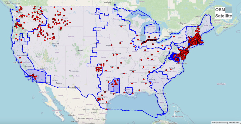
What you see below is a functionality-first view of the FCC licensing system mapping as much of the AMTS stations licensed or operating in the 219-220MHz band as can be found in the database.
It’s not perfect – working on data from other people and systems that you have no control over never is – but it’s much better than all existing alternatives.
Other Projects
It’s expected this would be useful for redoing W5NYV’s exploration into the demographics of Amateur Radio operators in the US: https://github.com/Abraxas3d/Demographics
Similarly, it might be very interesting to plot ALL the LO, PC, and other entries, and then merge in the other data that isn’t in the FCC database, like ham radio repeaters, to try to make the radio services in the ether around you that much more legible.
Some entries are not easy to import into the database, or have data errors that make them difficult to plot on the map. Those entities are not presently accounted for.
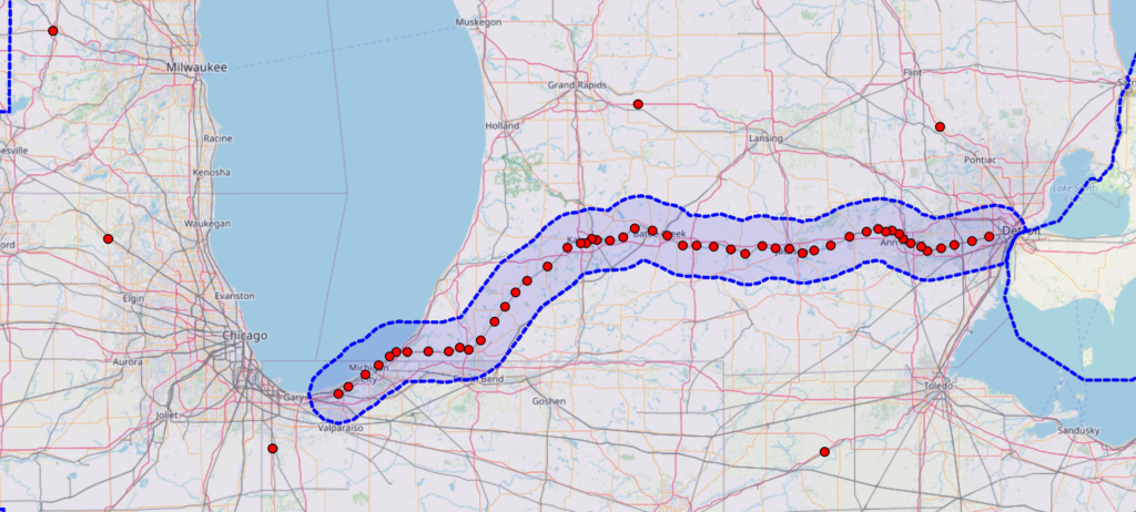
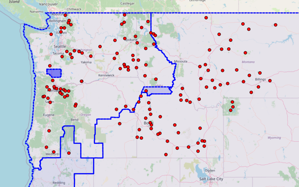
Above, AMTS stations in the United States. Below, a few detail images from the map, which can be found at https://amts.rf.band (heavy data, be patient for first load).
An article from ORI called “Space Frequency Block Coding Design for the Neptune Communications Project” will be in the January-February 2025 issue of QEX Magazine, from ARRL. Thank you to ARRL for publishing open source work from ORI.
Article Summary
The article discusses the design and implementation of Space Frequency Block Coding (SFBC) in the Neptune Communications Project, a digital radio initiative operating at 5 GHz for amateur radio applications.
Key Concepts and Objectives:
SFBC is a technique used in digital communications to improve signal resiliency by leveraging spatial, frequency, and coding diversity. It is commonly implemented in systems using Orthogonal Frequency Division Multiplexing (OFDM), utilizing multiple antennas for diversity. The mathematics are explained step-by-step with diagrams and equations. Noise calculations worked out in an Appendix.
Amateur Radio Application:
The Neptune project focuses on transmitting robust digital signals in noisy environments, essential for drone and aerospace communications. SFBC increases the likelihood of data recovery by mitigating multi-path interference and improving signal-to-noise ratio (SNR). An open source OFDM modem is needed in amateur radio.
Technical Details
Implementation:
SFBC transforms transmitted signal samples mathematically before sending them via two transmit antennas. Multi-path and spatial diversity enhance signal integrity against environmental reflections and interference.
Operation:
Signals are transmitted using OFDM, where subcarriers provide frequency diversity. The encoding does not increase throughput on its own but makes it easier to achieve maximum throughput performance.
Coding techniques like the Alamouti scheme are explained, with diagrams, for creating and decoding signals.
Trade-offs:
SFBC reduces SNR by 3 dB compared to optimal techniques like Maximum Ratio Combining but avoids the need for channel state knowledge at the transmitter.
Practical Implementation: SFBC was modeled and tested in MATLAB/Simulink, with plans for FPGA and ASIC implementations.
Future work includes:
Expanding to Space Time Block Coding (STBC).
Live demonstrations of SFBC/STBC performance differences.
Open-source release of HDL source code for hardware implementations.
Call to Action:
The Neptune project is a volunteer-driven, open-source initiative under the Open Research Institute (ORI). Community participation is encouraged, providing educational and developmental opportunities in digital communication technologies.
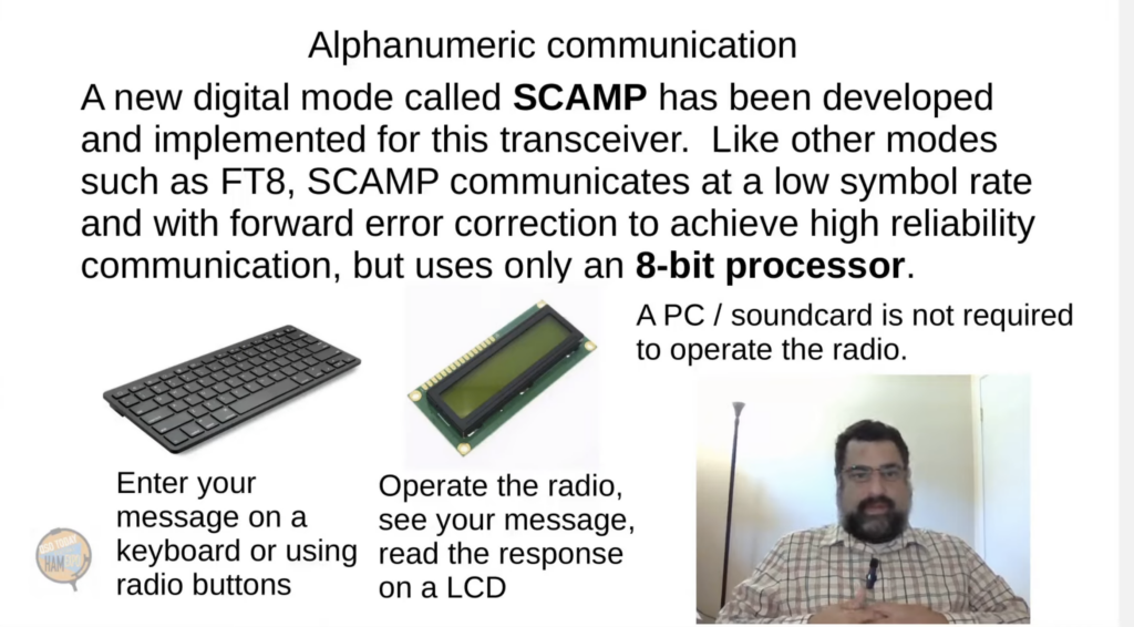
And then… let us tell you that SCAMP is now in FLDigi!
SCAMP is now even easier to use. If you want to get involved with this new mode and also build your skills with a very special low power HF radio kit, please visit our eBay listing for kits at https://www.ebay.com/itm/364783754396
A Tale of Troubleshooting
Problem Solving our Minimum Shift Keying Implementation in the Lab by Team OPV
Minimum shift keying (MSK) is the modulation used by Opulent Voice, our open source uplink protocol for our space and terrestrial transceiver. Unlike some other modulations, there aren’t a lot of documented and working examples of MSK, despite the many advantages of using this modulation for space and terrestrial channels. One of our educational goals at ORI is to provide exactly that, a documented and working example of MSK, that also delivers useful functionality to the amateur radio satellite service.
In the process of writing down a description of what happens mathematically, so that software defined radios like the PLUTO SDR can transmit and receive our Opulent Voice protocol, there’s been quite a few troubleshooting sessions. One session solved a problem where the main lobe bandwidth was too large. Another session solved a problem where the processor side code didn’t properly configure the radio chip. Another session switched to the correct version of LibIIO, or Library of Industrial Input and Ouput routines. The wrong library meant that the radio was “sort of” working, but not completely.
Troubleshooting and debugging systems is where most volunteer engineering time is spent. This is no different from professional development, where blank-paper time spent writing down routines may be a small fraction of the total development time of a project.
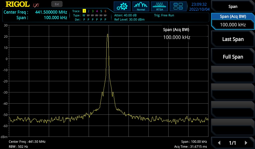
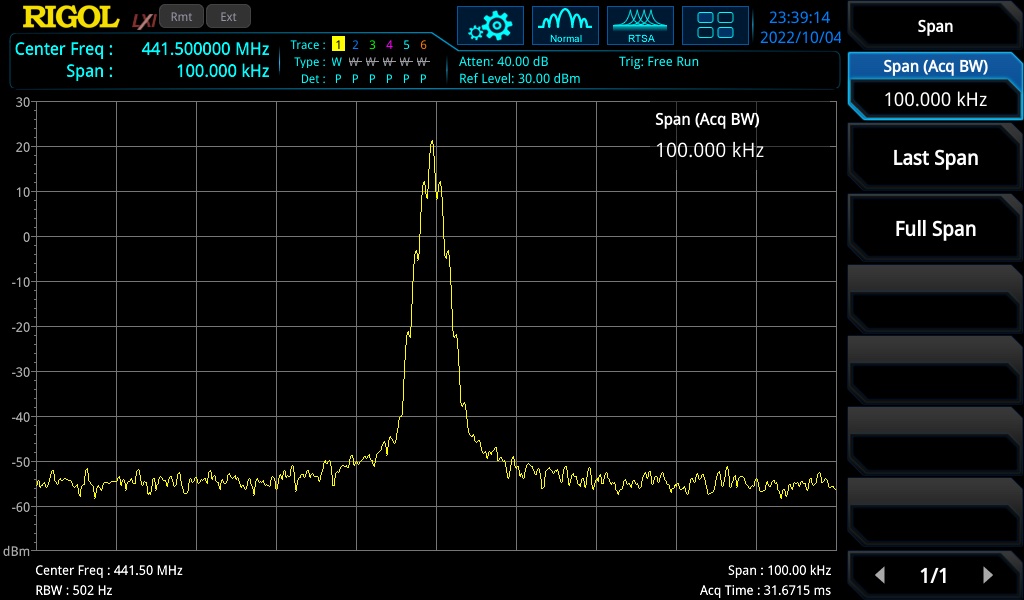
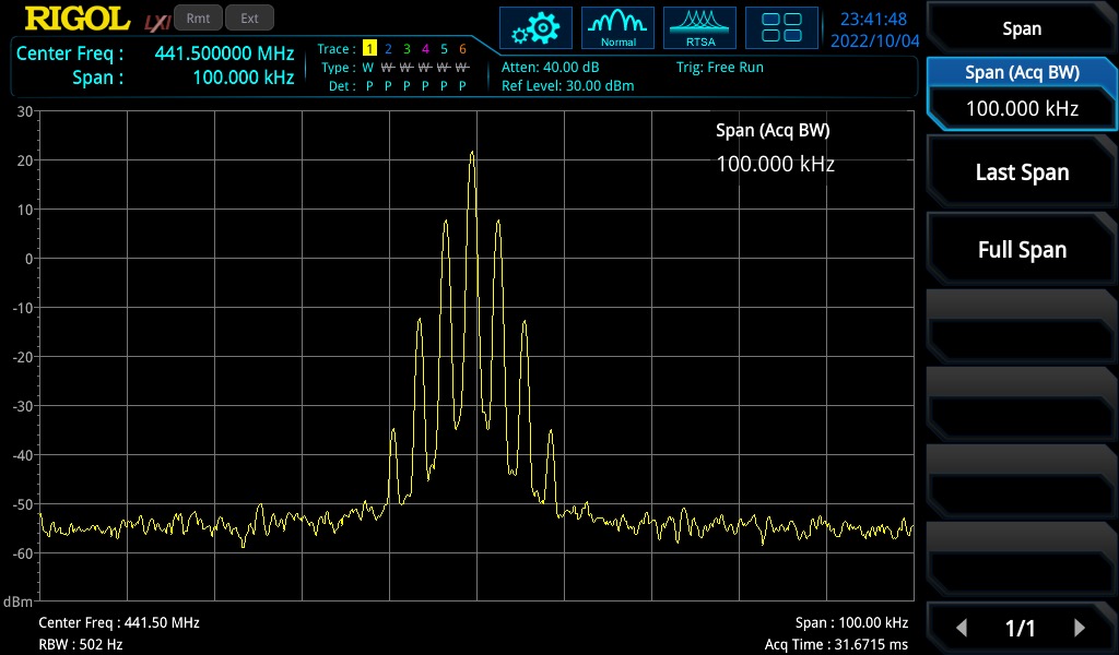
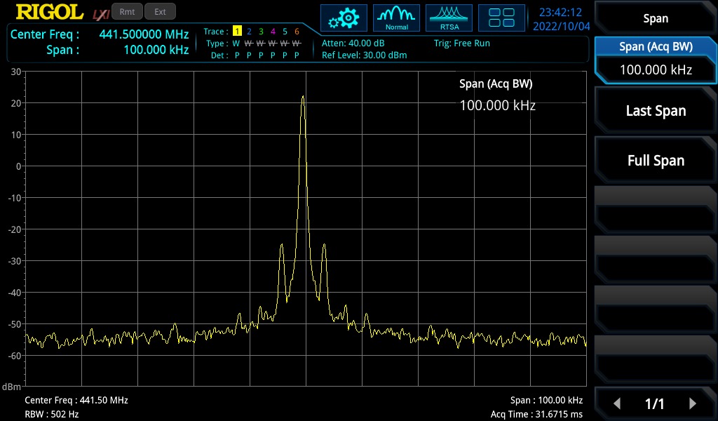
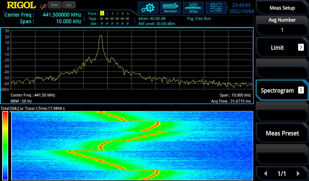
It can take multiple attempts to solve a problem. When this happens, it’s important to back up completely and recheck basic assumptions. Looking at the images below, one can see the desired MSK spectrum at the top. On the bottom is an example of an undesirable spectrum. The main lobe is bifurcated and the sidelobes have extra power. If you look at the graph, you can see that the sidelobes are higher in the “bad” example than they are in the “good” example. These are all clues, and there are several ways to go about attempting to solve the problem. The bad or “split” spectrum seemed to show up at random times, but it would go away when new PI controller gain pairs were written to the radio.
Why were we writing new proportional and integral gains to the radio? We were trying to tune our PI Filter, which is in the Costas Loop, which is in charge of tracking the frequency and phase of our signal so we can demodulate and decode successfully. We wrote code to search through proportional and integral gain pairs, testing their performance both in digital loopback and in loopback over the air.
After reviewing the code, asking for help, getting a variety of good advice, and trying to duplicate the problem in MATLAB, the problem unexpectedly went away when the processor side code was updated to remove extra writes to MSK block configuration registers.
The lessons learned?
* Clean code that matches the design of the hardware may prevent unexpected behavior. Don’t be sloppy with your test code!
* Keep up to date on changes in register accesses and behavior. There was a change from setting and clearing a bit in a register to the bit being toggled. This was a change from the level being important to the change in the level being important. Do your best to match what’s in the hardware!
Below, the “bad” spectrum as observed in the lab.
Below, the “good” spectrum, which returned after what we thought were unrelated code changes.
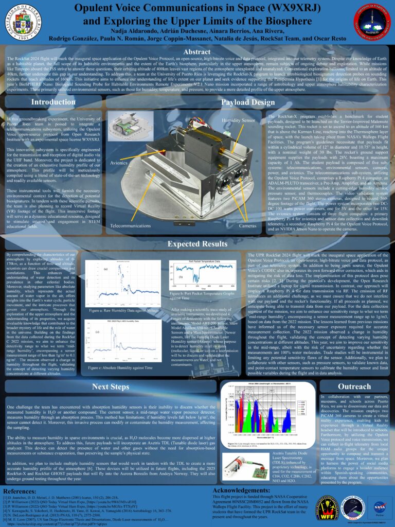
Opulent Voice at University of Puerto Rico
An Educational Success Story
by Michelle Thompson W5NYV with Oscar Resto KP4RF
Oscar Resto is an Instrumentation Specialist at the University of Puerto Rico’s Department of Physics. He also serves as the Principal Investigator for the university’s RockSat-X program. RockSat-X is a highly-regarded and very successful educational program sponsored by NASA and the Colorado Space Grant Consortium at the University of Colorado at Boulder. RockSat-X offers university and community college teams the opportunity to develop experiments for suborbital rocket flights, fostering innovation and practical experience in space-related fields.
Beyond his academic roles, Oscar is active in the amateur radio community, holding the call sign KP4RF. He has been involved in initiatives such as renewing the Memorandum of Understanding between the ARRL Puerto Rico Section and the American Red Cross Puerto Rico Chapter and has presented to a wide variety of audiences about amateur radio and emergency communications during and after major hurricanes.
The University of Puerto Rico has actively participated in NASA’s RockSat-X program since 2011, providing students with hands-on experience in designing, fabricating, testing, and conducting experiments for spaceflight. UPR’s RockSat-X team has developed increasingly complex experiments over the years. In 2011, UPR’s inaugural RockSat-X project utilized mass spectrometry to analyze atmospheric particles and pressure. Subsequent payloads have continued to evolve and refine the investigation of the “middle atmosphere”, an often-overlooked layer in atmospheric studies.
Oscar’s engineering design philosophy is to put the program in the hands of the students. The students are fully involved from the beginning of the process until launch. Oscar supports and enables consistent student success in two ways. First, by using the Socratic method of asking questions to lead the students through the many stages of design, test, documentation, and build. Second, by communicating clear expecatations about process and deadlines. Students source parts, build components using a wide range of manufacturing processes, and program all of the control and embedded devices. They carry out testing at the component, module, and end-to-end systems level. The student interface with NASA through meetings and regular reports.
Recent missions included deploying sterilized collection systems into the space environment to gather organic molecules, such as amino acids, proteins, and DNA, from altitudes between 43 to 100 miles above Earth. To ensure the integrity of collected samples, the team implemented innovative decontamination procedures that were carried out in flight.
For the 2023 and 2024 UPR RockSat-X entry, Opulent Voice was included as a communications payload. That version was a 4-ary FSK modulation, voice only, and ran on a general-purpose processor. In 2023, the rocket experienced a failure. In 2024, the mission was a complete success, with Opulent Voice received on a student-built and crewed portable station near the launch site. For 2025, assuming UPR’s RockSat-X application is accepted by NASA, the Minimum Shift Key (MSK) version of Opulent Voice, implemented on an FPGA and deployed on a PLUTO SDR, will be used by the student build team. This MSK version is much more advanced and more spectrally efficient.
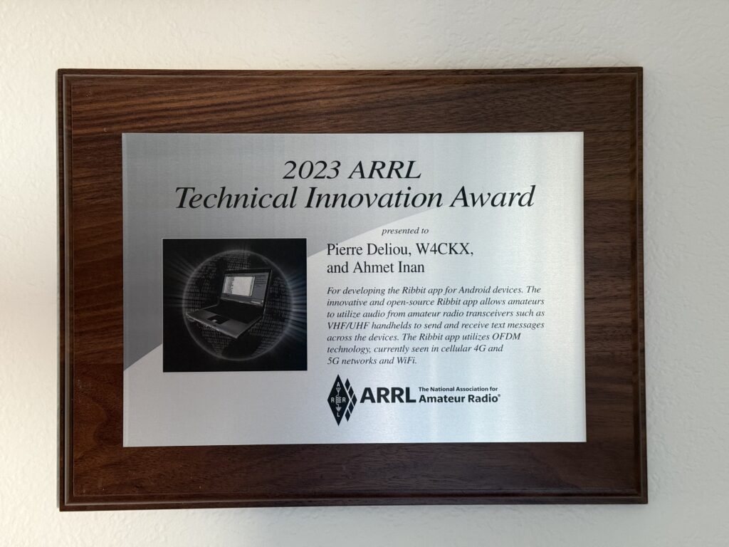
Shipment was delayed, but a nice surprise for Ribbit has finally arrived. Below is the plaque for Ribbit’s 2023 Technical Innovation Award.
The metal surface has black lettering and an image of a laptop computer. The body of the plaque is a handsome hardwood.
The text reads “For developing the Ribbit app for Android and iOS devices. The innovative and open-source Ribbit app allows amateurs to utilize audio from amateur radio transceivers such as VHF/UHF handhelds to send and receive text messages across the devices. The Ribbit app leverages OFDM technology currently used in cellular 4G and 5G networks & WiFi.”
Below, the plaque hanging on the wall in Remote Lab West.
Remote Labs are test benches with spectrum analyzers, oscilloscopes, power and frequency meters, FPGA development stations, power supplies, and multiple SDRs. The equipment is supported by a computer running virtual machines with a variety of operating systems to support software, firmware, and hardware development. Remote Labs are available 24 hours a day, 365 days a year for open source development.
Thank you to Pierre and Ahmet for all the extremely hard work to make Ribbit so successful!
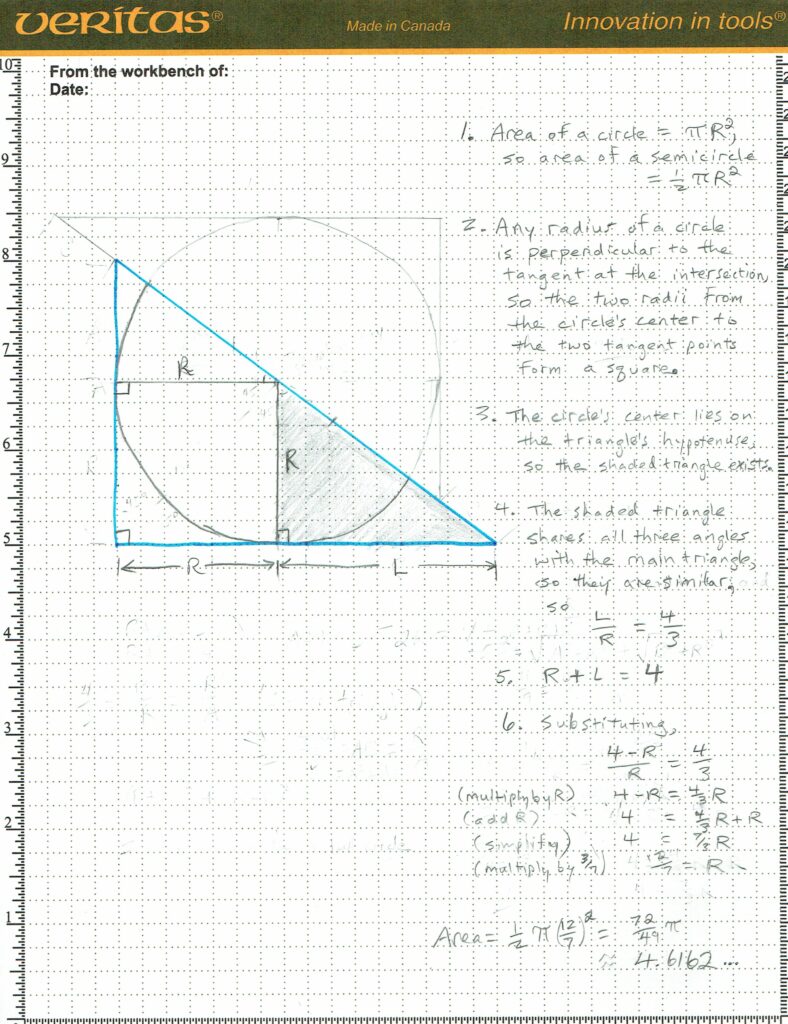
Given a 3, 4, 5 right triangle, with an inscribed semi-circle, where the hypotenuse of the triangle bisects the circle to form this semi-circle, find the area of this semi-circle.
Spoiler! The worked-out solution by Paul Williamson KB5MU is below.
The Inner Circle Sphere of Activity
December 17-22 2024 – Open Research Institute participates on the Federal Communication Commission’s Technological Advisory Council (TAC). Working groups composed of volunteers from industry, academia, and open source (ORI) meet weekly and debate and deliver advice to the FCC quarterly. This hybrid meeting is streamed on the FCC website.
December 31, 2024 – Fiscal year ends for Open Research Institute. Work begins on filing 2024 IRS 990 returns, which are due May 15, 2025.
December 20, 2024 through January 6, 2025 – Holiday Break for all labs and teams.
March 6, 2025 – Open Research Institute celebrates another birthday with parties planned so far in the US, Canada, and Europe. Sign up for a fun day commemorating open source volunteers around the world by writing hello@openresearch.institute.
Thank you to all who support our work! We certainly couldn’t do it without you.
Anshul Makkar, Director ORI Frank Brickle, Director ORI Keith Wheeler, Secretary ORI Steve Conklin, CFO ORI Michelle Thompson, CEO ORI Matthew Wishek, Director ORI
Thank you to everyone reading this that has supported ORI and how we publish our work on YouTube.
I know YouTube is not for everyone, but it is an effective way to communicate what we do, what challenges we face, and it lets people know there’s a community out there 1) doing things that they might find wonderful and 2) is worth hearing more about.
We have 400 subscribers, which is a bit of a milestone. This is a lot for a very technical all-volunteer organization that devotes its time supporting and promoting project work, while staying firmly in the background.
Our proudest moments are when projects succeed and are recognized on their own merits, under their own name, and under their own branding. Ribbit, RFBitBanger, Haifuraiya, a variety of published Open Source FPGA work, FPGA training, Opulent Voice, Versatuner, Dumbbell, actively participating in IEEE, FCC TAC membership, Remote Labs, our many regulatory successes, and our active and successful mentoring in professional and academic settings – these are all clear indications that we’re on the right track and doing a great job.
Not explicitly mentioned are the many places we’ve helped projects succeed behind the scenes, around the world.
We are committed to an altruistic approach that delivers clear value to project work. This approach has been abused only once, by one organization.
Being accountable, open, and successful is the cost of doing our type of business. This is a price happily paid.
The interleaver for Opulent Voice needs to be updated because the frame size has increased. We are incorporating RTP, UDP, and IP layers into the existing OPUS and 4-ary MFSK layers and now have what we think may be the final frame size.
Since convolutional encoding is used for Opulent Voice payload, an interleaver is necessary to get the best bit error rate performance out of the convolutional encoder. The interleaver is used over both the physical layer header (Golay encoded) and the data payload (a 1/2 rate Convolutional code). Opulent Voice is an open protocol that we use for our HEO/GEO uplink. It can also be used terrestrially on the #hamradio bands at 70cm and above. Find out more at https://www.openresearch.institute/2022/07/30/opulent-voice-digital-voice-and-data-protocol-update/
The distance that an interleaver spreads out bits in a frame is the most familiar performance measurement. It’s commonly called “spread” or “minimum interleaved distance”. However, we learned about another metric that is important in Turbo codes. Several papers refer to the measure of randomness of the mixture of bit position reassignments as “dispersion” (for example, see https://cgi.tu-harburg.de/~c00e8lit/cgi-bin/ivpub/download.php?file=kb-wpmc2008.pdf). That particular paper cited another paper (reference [6]) as defining dispersion.
Following that citation lead to a paper but this paper didn’t mention dispersion or explain the equation. Going back to the original paper, we started working with the definition for dispersion that we had. This used the cardinality of the set of indices of original bit positions vs. permuted bit positions. This seemed straightforward enough. But, after trying this in MATLAB, we always got the minimum dispersion value, so there must be something wrong with our interpretation.
Volunteers then spent time trying to figure out if dispersion is important enough metric for a single convolutional code, like we have in #OpulentVoice. In other words, should we simply not simply choose the polynomials that result in the largest minimum interleaved distance? Selecting the right interleaver based on a balance between how far apart it spreads the bits vs. how randomly the bits are distributed is a useful selection methodology for Turbo codes, but may not be strictly necessary for a single convolutional code used with 40 mS frames.
Everyone is welcome to join in the discussion and work to create quality #OpenSource work for #digital communications at ORI. Please see https://openresearch.institute/getting-started to be welcomed to our community.
Thank you so much for your time, attention, and support. We appreciate you, we welcome your feedback, and we are dedicated to serving the community to the best of our abilities. You can get in touch with the ORI board of directors directly at hello@operesearch.institute.
A Puzzle Just For Fun
Here’s a puzzle. Chicken Nuggets have been on the menu at the international fast food chain McDonald’s since 1983.
If Chicken McNuggets are sold in packs of 6, 9, or 20, then what is the largest number of nuggets that cannot be ordered?
Answer is at the end of this newsletter!
Projects
Our volunteer teams have been busy and successful, and our project lineup has grown.
Regulatory Efforts: ORI works hard to promote and defend open source digital radio work. We do all we can to help move technology from proprietary and controlled to open and free. Our work on ITAR, EAR, Debris Mitigation, and AI/ML are where we have spent most of our time over the past two years. We were a member of the Technological Advisory Committee for the US Federal Communications Commission in 2022, and co-chaired the Safe Uses of AI/ML Subworking Group. We have received consistently positive reviews for all of our work, and there has been increasing use of the results.
Ribbit: this open source communications protocol uses the highest performance error correction and modern techniques available to turn any analog radio into an efficient and useful digital text terminal. No wires, no extra equipment. The only thing you’ll need to use it is the free open source Android or IoS app on your phone. Learn how to use this communications system and get involved in building a truly innovative open source tactical radio service by visiting https://ribbitradio.org
Amateur Satellite: ORI has the world’s first and only open source HEO/GEO communications satellite program, called Haifuraiya. We will demonstrate all working parts of the transponder project at DEFCON 31, where broadband digital communications and open source electric propulsion will be featured. Find out how to support or join this and other teams at https://openresearch.institute/getting-started
AmbaSat for 70 cm: We’ve redesigned the AmbaSat board to move it from 915 MHz to 70 cm and it will be flown on a sounding rocket this year. With increasing interest in LoRa for both space and terrestrial use, this has proven to be a popular and useful project. The design has been adapted for applications in India and Japan.
Opulent Voice: a digital protocol that seamlessly combines high fidelity voice and data, using modern forward error correction, authentication and authorization, and efficient minimum frequency shift keying modulation. Opulent Voice will be flown on a sounding rocket this year and it is the native digital uplink protocol for Haifuraiya. Completely open with the high quality voice we deserve to hear. Due to the bandwidth requirements of the 16kHz OPUS codec, Opulent Voice can be used on 70cm and above ham bands, or anywhere else where the modest bandwidth requirements can be met.
Remote Labs: We have two remotely accessible workbenches for FPGA development, with Xilinx 7000 and Xilinx Ultrascale+ development boards as the focus. We also have several SDRs and radio utility devices available through virtual machine access. The 7000 series development board has an Analog Devices ADRV9371 radio system attached, and that has enabled a number of open source FPGA products to be published. This is a unique resource that has produced a lot of good work and is constantly being improved and updated. In addition to the development boards, the laboratory has a network accessible spectrum analyzer, an oscilloscope with logic analyzer extension, power supplies, frequency and power counters, and dedicated human resources available to help students, volunteers, or professionals contribute to open source work. Help it be more useful by spreading the word about ORI Remote Labs.
Versatune: amateur digital television next generation hardware and software product. It is open source and affordable. We have committed engineering resources to support Versatune and are very excited about how things are going. Some of the Versatune team will be at Hamvention 2023 in Xenia, OH, USA, and it will be represented at DEFCON in August 2023.
HF antennas: We have a novel foldable antenna design for space and terrestrial use. The hardware prototype will be demonstrated at DEFCON. This design manipulates radiation resistance to produce best-of-class results. Think you can’t do 160m without an enormous antenna? Think again.
HF QRP: Coming soon, an exciting HF QRP digital radio board and protocol. The hardware prototypes will be demonstrated at DEFCON. What might happen when we combine the HF digital radio with the novel foldable antenna? We think you’ll be delighted.
Battery Matching Curves: are you available to mentor a college student interested in learning how to match up charge and discharge curves from NiCd cells in order to create battery packs? These packs would then be tested and/or deployed in the field. Our student volunteer has collected the data and is looking to learn how to use Jupyter Notebooks to select the cells to create battery packs.
Logistics
We’re growing and adapting!
We will be changing our GitHub project name from Phase4Ground to Open Research Institute very soon. Phase4Space GitHub project will change to Haifuraiya, which is the program name for our HEO/GEO design. These changes better reflect the content and purpose of the 64 repositories that span everything from important historical archives to open source music to the most modern open source encoders available.
We have a very well-qualified applicant for our open board of directors position. We would like to invite interested community members to consider applying to ORI in order to expand the board beyond this filled position in order to take us from our current five members to seven. Given our continuing growth, a larger leadership team would ensure continued smooth operations. These positions are unpaid, engaging, and can be demanding. The most important skill set is a strong sense of ethics and service.
Fundraising and Grants
We’ve applied for the GitHub Accelerator Program (Remote Labs) and the IEEE Innovation Fund (Polar Codes in Ribbit). If you have a recommendation for ORI in terms of partnerships or collaboration, please let us know at hello@openresearch.institute
Support ORI financially directly through the website https://openresearch.institute. There is a PayPal donation widget at the bottom of almost every page. Donations can be directed to any project, or to general operations. ORI has a very low overhead, with most projects coming in under 5%.
We’ve raised enough money to cover materials for machining the engine parts. The next step is to raise enough money to pay for the electronics. Please help spread the word!
Thanks to our wonderful community, we have employee matching in place at Microsoft and Qualcomm. If you have an employee matching program at your work, and you think ORI would fit in, please consider nominating us. Our EIN is EIN: 82-3945232
Events
Where can you meet up with ORI people?
QSO Today Ham Expo
We support and attend QSO Today Ham Expo, held online 25-26 March 2023. The theme of this event is “New License, Now What?” and focuses on people new to amateur radio.
Join us at the amateur radio social at the International Microwave Symposium (IMS2023) on Tuesday 13 June 2023 in San Diego, CA, USA at 6pm. It will be held in a beautiful outdoor venue with food and drink provided. The easiest way to register for this event is to purchase an exhibition badge and then sign up for the social. https://ims-ieee.org/ is the event website.
DEFCON
We are getting ready for our biggest event of the year. We have proposed an in-person Open Source Showcase to RF Village for DEFCON 31 in Las Vegas, Nevada, USA from 10 – 13 August 2023.
IEEE wants to bring together all participants to take full advantage of CHIPS Act funding. IEEE will have an Innovative Workforce Resources Conference in Little Rock, AR 13-14 September. There will be a reception at the Clinton Presidential Library, and attendees will enjoy the best BBQ in the country. The National Science Foundation requires that a certain percentage of funding has to be spent in states that don’t get their fair share of research money. The goal of this conference is to pull together small researchers from small business like ORI and do research, with Arkansas as a focus.
We couldn’t agree more. After all, we are putting a lot of time and energy into Remote Labs South, located just outside Little Rock, AR. Bringing innovative open source digital radio work to students, workers, and volunteers that need it the most simply makes sense. If you can attend IWRC 2023 and help represent ORI please get in touch. We will be reaching out to IEEE chapters in Arkansas as well.
43 is the largest number of nuggets that cannot be ordered.
What is the largest number of McNuggets that you can’t buy with packs of 6, 9 and 20? After putting in their blood, sweat, and tears, the mathematicians found that the answer is 43. You cannot buy 43 nuggets with packs of 6, 9 and 20, but you can buy any amount larger than 43.
Robert C. Baker invented the chicken nugget, among many other things. He was a true innovator of what can be fairly called “modern foods”. A brief wikipedia article about him can be found here: https://en.wikipedia.org/wiki/Robert_C._Baker
Do you have an idea for an interdisciplinary puzzle for our next newsletter? We’d love to hear about it. Write ori@openresearch.institute
Until Next Time
Thank you so much for being part of our Inner Circle! You are the motivation for all of this work, provided to the general public for free. We believe it makes the world a better place.
We hope to see you again at QSO Today Ham Expo this weekend, 17-18 September 2022. We have a booth, five talks, three project exhibits, and a lounge space for meet and greet.
Since the last Ham Expo, we’ve integrated the DVB-S2/X encoder into the downlink reference design for our open source broadband microwave transponder. We have started on the uplink receiver. We have published a specification for our high bitrate digital voice and data uplink protocol. It’s called Opulent Voice and it will be introduced and described at the Expo. Find the source code for a C++ implementation at https://github.com/phase4ground/opv-cxx-demod
We have two sounding rocket projects, an open source propulsion project, successful regulatory work, and we represent open source and amateur radio interests on the US FCC Technological Advisory Committee. We co-chair the “Safe Uses of AI/ML” subworking group.
Our open source HEO proposal Haifuraiya will be presented at the Expo this weekend and details will be in an upcoming JAMSAT Journal.
We do terrestrial communications as well! Ribbit is a digital emergency communications mode for VHF/UHF. No extra equipment or cables required. We have a poster about the project in the exhibit hall and a presentation. Get the free Android application at https://play.google.com/store/apps/details?id=com.aicodix.rattlegram
All video presentations will be available at our YouTube channel after the Ham Expo platform has closed in 30 days.
We have a mailing list for updates and discussion, a Slack account for engineering work, and all work is published as it is created to our GitHub account.
If you’d like to get monthly newsletters like this one, then do nothing. You’re already part of the inner circle!
Our volunteers could not accomplish all of this wonderful work without your interest and support.
Thank you from everyone at ORI. We value your comment, critique, and feedback, and look forward to hearing from you. If you use social media, then a lot of what we do is published through the channels linked below.
We measured the deviation limits on the MD-380 with firmware from OpenRTX. Thank you to Redman for help with modifying the firmware to make this test as easy as possible.
The transmitted signal is about 10 dB down at 3000 Hz and almost gone at 4200 Hz. Therefore, there is not enough deviation for Opulent Voice.
The part of the radio under test was the HR_C5000. This is a part from Hong Rui and is a DMR digital communications chip. The chip handles 4FSK modulation and demodulation, among other functions.
According to a translated datasheet for the HR C5000, adjustment of the frequency offset range not possible. It appears to be designed only for +/- 3 kHz. Unless there’s an undocumented feature, or gain is added after the HR C5000, then +/- 3 kHz is the maximum deviation for this radio.
The HR C5000 puts out two analog signals MOD1 and MOD2, which are combined and then drive a varactor diode. The varactor might well have more range. Or it could be replaced with one that has more range.
Below is a photo essay of the testing and screenshots of results.
30 AWG wire soldered to pin 5 of the HR_C5000 on the MD-380. This is one of two audio inputs to the modulator. It’s the one used for signaling tones, and not the one used for microphone audio, in the original design. Ground wire attached as well and brought out. Firmware modifications disabled M17 baseband output when PTT pressed. Pre-emphasis and filters disabled by putting radio in M17 mode. The red wire is part of the standard M17 mod for the MD-380.Ground wire attached to point on board and brought out. Modifications inspected by KB5MU in Remote Lab. The black rubbery weather seal gasket around the perimeter of the cast heatsink means there’s no way for wires, even very skinny ones, to come out through the seam in the case.Hole was drilled in the side of the case and the wires brought out. Radio was put back together. Battery, display, etc. all working after modifications. Notice the 20 dB attenuator on the output of the HT. Its lowest output power is 1W nominal, which matches the maximum rated input of the spectrum analyzer, so the attenuator was added to protect the spectrum analyzer’s front end. Test setup.
Test Results
Transmitted signal before modified firmware.Transmitted signal after modified firmware. Notice no modulation because the baseband signal has been disabled. 1kHz sine wave at 100 mV injected to pin 5 of the HR C5000.1kHz sine wave at 220 mV injected to pin 5 of the HR C5000.3 kHz sine wave at 220 mV injected to pin 5 of the HR C5000. Signal is about 10dB down at 3 kHz4200 Hz sine wave at 220 mV injected to pin 5 of the HR C5000. Signal is approximately 45 dB down. Looking at the low end, this is one half a Hz at 220 mV injected to pin 5 of the HR C5000.Two tenths of a Hz at 220 mV injected to pin 5 of the HR C5000. Notice the discontinuities. These were not seen when the signal generator was connected to an oscilloscope. It could be that when the modulating frequency is too low, it interacts with a PLL or other frequency stabilization loop in the radio. It would not be an issue in the original design, with all audio coupled through capacitors. No way anything that close to DC would get to the audio chip.
This Opulent Voice sticker is available from ORI at events around the world.
Opulent Voice is an open source high bitrate digital voice (and data) protocol. It’s what we are using for our native digital uplink protocol for ORI’s transponder project. Opulent Voice is also looking pretty darn good for terrestrial.
Here is an audible example of the Opulent Voice audio quality under ideal conditions. Each file is about 37 seconds long. It starts with a short musical intro, and the rest is the beginning of the audio track from one of Michelle’s conference talks. These were originally recorded with mid-range podcasting studio gear. The recording was converted to a signed 16-bit PCM raw file, which has been re-converted to a standard WAV file so you can play it easily, MDT-short.wav
Original recording
This file was then run through opv-mod to create a file of baseband samples, which was then piped to opv-demod, which created an output file of signed 16-bit PCM. That file was converted to WAV file MDT-short.demod.wav
Original recording modulated and then demodulated through Opulent Voice.
We expect to present a nice demo at DEFCON in August 2022 and at the QSO Today Ham Expo in September 2022.
We’ll be using COBS protocol within Opulent Voice. If you’re unfamiliar with COBS, please read about it here:
Authentication and authorization is built in and optional. There is no separate “packet mode”. Things are designed to “just work” and get out of your way whether or not you’re sending voice or data.
Opulent Voice is designed to where you can use even higher bitrate OPUS codecs if you wish. This will most likely be a build option and not a run-time option, but if a run-time option is something you want to work on, speak up! Let’s see what we can accomplish.
Originally based on Mobilinkd codebase that implements M17, the Opulent Voice development implementation can be found here:
Initial demos will be on a HackRF/PortaPack on the 1.2 GHz ham bands.
Thank you to OpenRTX for help with troubleshooting the audio quality on the PortaPack. In order to have a good demo, basic FM transmit from the microphone needs to work. The audio quality is pretty bad (this was a surprise) with the stock application, so we’ve been spending some time with the Mayhem codebase, the microphone transmit app, and the driver for the audio codec in order to get it sounding like it should. This needs to happen before we publish an app for the PortaPack.
Synthesized audio from the HackRF/PortaPack sounds clear and wonderful. It’s just the microphone that is splattery and overdriven.